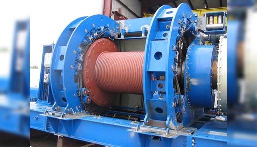
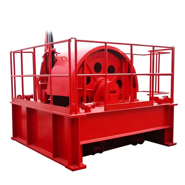
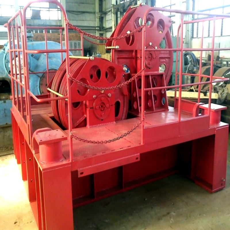
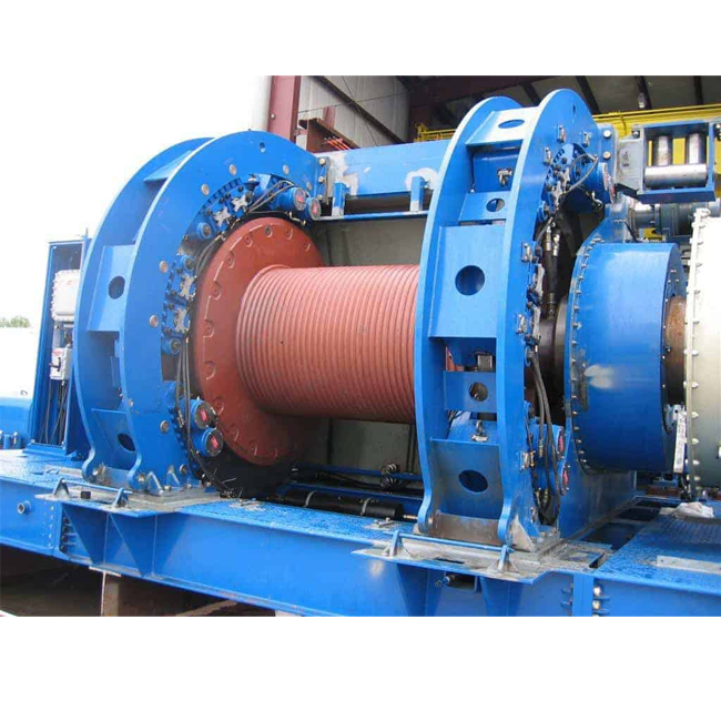
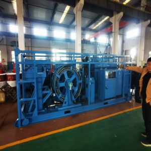
Draw works
1. Drawworks is the core component of oil drilling rig, it is mainly used for sending in drill tool,lifting derrick, tripping and casing and other operations during drilling.
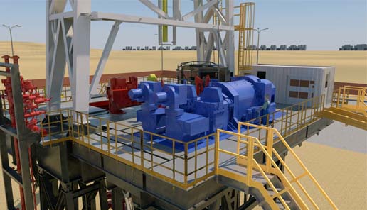
2. The drawworks can be driven by mechanical drive and electric drive. The main and auxiliary brakes are reasonably configured to meet the requirements of power transmission and drilling workover operation.
3. The drawworks and its power unit can be installed on one skid for separate transportation.
4. The brake disc is forced cooled by circulating water, and the surface is quenched by medium frequency, with good wear resistance and long service life.
5.Consist: Drum and shaft assembly, brake system, cathead assembly, transmission assembly, Control system, lubrication system etc.
Model of rig | JC40D | JC50D | JC70D | |
Nominal drilling depth, m(ft) | with Ф114mm (4 1/2”) DP | 2500-4000 (8200-13100) | 3500-5000 (11500-16400) | 4500-7000 (14800-23000) |
with Ф127mm(5”) DP | 2000-3200 (6600-10500) | 2800-4500 (9200-14800) | 4000-6000 (13100-19700) | |
Rated power, kW(hp) | 735 (1000 ) | 1100 (1500 ) | 1470 (2000 ) | |
Qty. of motors ×rated power, kW(hp) | 2 ×438(596)/1 ×800(1088) | 2 ×600 (816) | 2 ×800 (1088) | |
Rated speed of motor, r/min | 880/970 | 970 | 970 | |
Dia. of drilling line, mm(in) | 32 (1 1/2 ) | 35 (1 3/8) | 38 (1 1/2) | |
Max. fast line pull, kN(kips) | 275(61.79) | 340(76.40) | 485(108.36) | |
Main drum size (D×L), mm(in) | 640×1139 (25 1/4×44 7/8 ) | 685×1138 (27 ×44 7/8) | 770×1361 (30 ×53 1/2) | |
Brake disc size (D×W), mm(in) | 1500×40 (59 ×1 1/2) | 1600×76 (63 ×3 ) | 1600×76 (63 ×3) | |
Auxiliary brake | Electromagnetic eddy current brake/Eaton brake | |||
DSF40/236WCB2 | DS50/336WCB2 | DS70/436WCB2 | ||
Overall dimension(L×W×H), mm(in) | 6600×3716×2990 (260×146×118) | 6800×4537×2998 (268×179×118) | 7670×4585×3197 (302×181×126) | |
Weight, kg(lbs) | 40000(88185) | 48000(105820) | 61000(134480) | |
CROWN BLOCK
The crown block is an essential component in drilling rigs, designed to handle heavy loads and ensure safe, efficient operations. Our crown blocks are built to meet API 4F standards and comply with SY/T5527 industry requirements. They feature wire rope guards to prevent the wire rope from jumping or falling off the pulley, maintenance hoists for ease of repair, and sand line pulleys and auxiliary pulleys for additional functionality. The pulleys are interchangeable with their corresponding traveling blocks, enhancing operational flexibility.
Key Features:
- Compliance with Standards: Conforms to API 4F and SY/T5527 industry standards.
- Wire Rope Guard: Prevents wire rope from jumping or falling off the pulley.
- Maintenance Hoists: Equipped with hoists for pulley maintenance.
- Additional Pulleys: Includes sand line pulleys and auxiliary pulleys.
- Interchangeable Pulleys: Pulleys can be interchanged with corresponding traveling blocks for flexible operations.
Model | TC90 | TC158 | TC170 | TC225 | TC315 | TC450 | TC585 | TC675 | |
| Max. hook load kN (lbs) | 900 (200,000) | 1580 (350,000) | 1700 (37,400) | 2250 (500,000) | 3150 (700,000) | 4500 (1,000,000) | 5850 (1,300,000) | 6750 (1,500,000) | |
Dia. of wire line mm(in) | 26(1) | 29(1 1/8) | 29(1 1/8) | 32(1 1/4) | 35(1 3/8) | 38(1 1/2) | 38(1 1/2) | 45(1 3/4) | |
O.D. of sheaves mm(in) | 762(30) | 915(36) | 1005(40) | 1120(44) | 1270(50) | 1524(60) | 1524(60) | 1524(60) | |
Number of sheaves | 5 | 6 | 6 | 6 | 7 | 7 | 7 | 8 | |
Overall dimension | Length mm(in) | 2580 (101 9/16) | 2220 (87 7/16) | 2620 (103 5/32) | 2667 (105) | 3192 (125 11/16) | 3140 (134 1/4) | 3625 (142 3/4) | 4650 (183) |
Width mm(in) | 2076 (81 3/4) | 2144 (84 7/16) | 2203 (86 3/4) | 2709 (107) | 2783 (110) | 2753 (108 3/8) | 2832 (111 1/2) | 3340 (131 1/2) | |
Height mm(in) | 1578 (62 1/8) | 1813 (71 3/8) | 1712 (67) | 2469 (97) | 2350 (92 1/2) | 2420 (95 3/8) | 2580 (101 5/8) | 2702 (106 3/8) | |
Weight, kg(lbs) | 3000 (6614) | 3603 (7943) | 3825 (8433) | 6500 (14330) | 8500 (18739) | 11105 (24483) | 11310 (24934) | 13750 (30314) | |
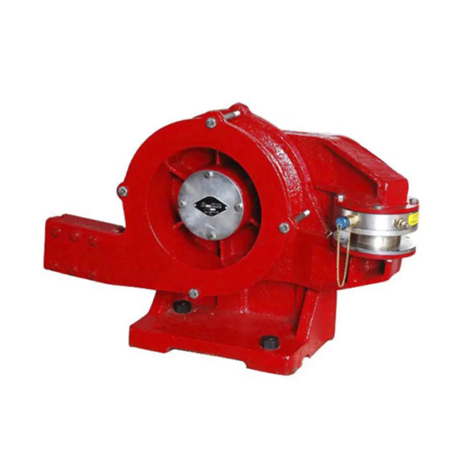
Air Winch / Hydraulic Winch
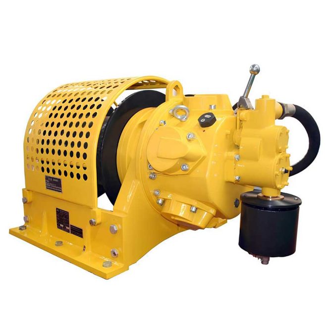
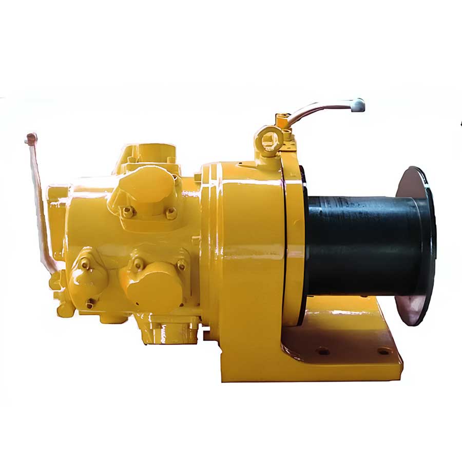
The pneumatic air winch we offer is a versatile tool driven by a piston air motor. It is primarily designed for use in oil, natural gas, and geothermal drilling. Its compact size, lightweight nature, high efficiency, ease of operation, and reliable safety make it indispensable for lifting or hauling heavy objects not only in drilling operations but also in various other applications.
| Model | QJL 0.5/40(A) | QJ0.5/120(A) | QJ1/100(A) | QJ3/200(B) | QJ5/220(B) | QJ5/220(B) | |
| Air Pressure | Mpa | 0.5-0.9 | |||||
| Psi | 72-130 | ||||||
| Max. Pull | kN | 5 | 10 | 30 | 50 | ||
| ton | 0.55 | 1.1 | 3.3 | 5.5 | |||
| Max. Line Speed | m/min | 12 | 24 | 12 | 35 | 20 | 12 |
| Ft/min | 39.3 | 78.6 | 39.3 | 114.8 | 65.6 | 35.3 | |
| Rope Storage | M | 40 | 120 | 100 | 200 | 120 | 220 |
| ft | 131 | 393 | 328 | 656 | 393 | 720 | |
| Wire rope dia. | Mm | 8 | 11 | 15.875 | 19 | ||
| in | 5/16 | 7/16 | 5/8 | 3/4 | |||
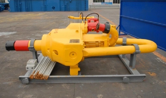
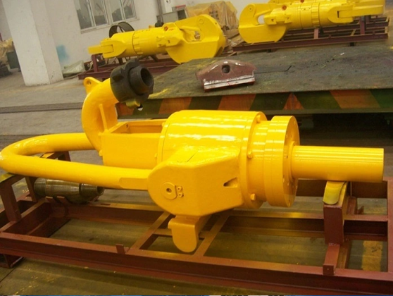
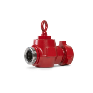
Drilling Swivel
Water Swivel for drilling: The swivel includes two main categories, which are common swivel and double duty swivel. Double duty swivel is a common swivel combined with a spinner. Common swivel consists of swivel bail, shell, support, gooseneck, central pipe, master bearing, joint and other parts. The lower end is connected with kelly stem by REG thread. The swivel bail is hung on the hook. Gooseneck and rotary hose can be connected by REG thread connection or union connection.
| Model | SL110 | SL135 | SL170 | SL225 | SL315 | SL450 | SL450A | LBC200 | LD300 | SL585 | |
| Max .static load | kN | 1100 | 1350 | 1700 | 2250 | 3150 | 4500 | 4500 | 1700 | 2600 | 5850 |
| US ton | 120 | 150 | 200 | 250 | 350 | 500 | 500 | 200 | 300 | 650 | |
| Dynamic load rating | kN | 600 | 1000 | 1300 | 1600 | 2100 | 3200 | 3200 | 1300 | 1500 | 4100 |
| US ton | 65 | 110 | 140 | 175 | 230 | 350 | 350 | 140 | 165 | 450 | |
| Max. Speed | rpm | 300 | 300 | 300 | 300 | 300 | 300 | 300 | 300 | 300 | 300 |
| Max .pressure | MPa | 35 | 35 | 35 | 35 | 35 | 35 | 35 | 35 | 35 | 35 |
| psi | 5000 | 5000 | 5000 | 5000 | 5000 | 5000 | 5000 | 5000 | 5000 | 5000 | |
| Gooseneck connection | 3LP | 4LP | 4LP | 4LP | 4LP | 4LP | 4LP | 4LP | 4LP | 4LP | |
| Sub connection | 4-1/2 REG-LH | 6-5/8 REG-LH | 6-5/8 REG-LH | 6-5/8 REG-LH | 6-5/8 REG-LH | 6-5/8 EG-LH | 6-5/8 EG-LH | 6-5/8 REG-LH | 5-1/2 REG-LH | 6-5/8 REG-LH | |
| Applicable spinner model | XSL135 | XSL170 | XSL225 | XSL315 | XSL450 | SL450A | XSLBC200 | ||||
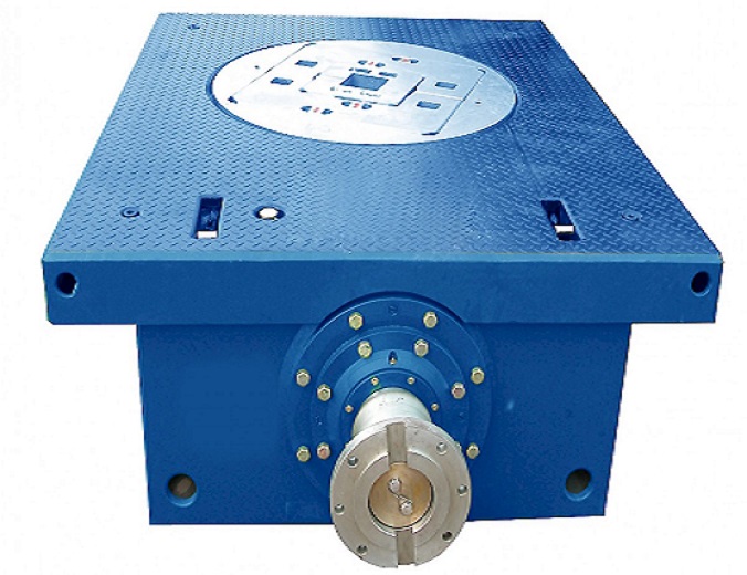
Rotary Table
The ZP series rotary table is vital in oil, gas, and geothermal drilling operations. It rotates the drill string and bears the weight of the pipe in the well. Designed and manufactured according to API Spec 7K, “Specification for Drilling Equipment,” the ZP series rotary tables are built to meet the demanding requirements of modern drilling operations. They are available in various models for load capacities and operational needs.
- Design and manufacture according to API 7K standard.
- Bevel gear pair use the spiral bevel gear, stable transmission, high capacity
- Gear material is alloy steel, Main shell is iron.
- Frame used the High strength steel material.
- Long service time.
- We also can be produce according to your request.
| Model | ZP375 | ZP275 | ZP205 | ZP175 |
|---|---|---|---|---|
| Max. Static Load | 5850 kN (650 US ton) | 4500 kN (500 US ton) | 3150 kN (350 US ton) | 2250 kN (250 US ton) |
| Through Hole Diameter | 952.5 mm (37-1/2 in) | 698.5 mm (27-1/2 in) | 520.7 mm (20-1/2 in) | 444.5 mm (17-1/2 in) |
| Gear Ratio | 3.56 | 3.67 | 3.22 | 3.58 |
| Distance from Center of Rotary Table to Center of Inner Row of Sprocket Teeth | 1353 mm (53-1/4 in) | 1353 mm (53-1/4 in) | 1353 mm (53-1/4 in) | 1118 mm (44 in) |
| Size (L x W x H) | 2468 x 1810 x 718 mm (97 x 71 x 28 in) | 2392 x 1670 x 685 mm (94 x 66 x 27 in) | 2392 x 1475 x 668 mm (90 x 58 x 26 in) | 1935 x 1280 x 585 mm (76 x 50 x 23 in) |
| Weight | 8026 kg (17694 lb) | 6203 kg (13680 lb) | 5530 kg (12190 lb) | 3888 kg (8572 lb) |
HYDRAULIC DISC BRAKE
1. The brake caliper has sufficient brake reserve coefficient and reliable braking.
2. Various clearance adjustment methods can adjust the brake clearance conveniently, quickly and accurately.
3. The brake caliper is small in size, easy to install and maintain, and convenient to replace the brake pad.
4. High precision of brake control curve. Remote and automatic control can be realized.
5. The brake caliper meet the requirements of all kinds of drilling rigs and workover rigs under various working conditions such as land, ocean, desert and low temperature.
6. Air – cooled, water – cooled brake disc and strong – cooled brake disc are suitable for different drilling conditions.
7. The special brake pad has good friction performance and easy replacement.
| Category | Name | PS30 | PS40 | PS50 | PS70 |
| Working clamp | Maximum positive pressure on one side lbf | 11240.45 | 16860.67 | 20232.8 | |
| Effective stroke in | 1.18 | ||||
| Permissible minimum working thickness of brake pad in | 0.47 | ||||
| Overall dimension in | Φ5.90×9.52 | Φ7.08×11.41 | |||
| Weight lbs | 39.68 | 55.11 | |||
| Safety clamp | Maximum positive pressure on one side lbf | 11240.45 | 20232.8 | ||
| Maximum working clearance of brake pad in | 0.04 | ||||
| Permissible minimum working thickness of brake pad in | 0.47 | ||||
| Overall dimension in | Φ7.48×12.99 | Φ8.26×13.97 | |||
| Weight lbs | 77.16 | 105.82 | |||
| Hydraulic system | Rated pressure psi | 870 | 1160 | ||
| Working medium Summer | L-HM46 antiwear hydraulic oil | ||||
| Working medium Winter | L-HV32 low temperature antiwear hydraulic oil | ||||
| Rated flow rate of single pump L/min | 4.75 | ||||
| Oil tank volume L | 39.62 | ||||
| Motor power hp | 2.95 | ||||
| Accumulator capacity gal | 4×1.66 | ||||
| Heater power hp | 1.34 | ||||
| Cooling water flow rate gal /h | 528.34 | ||||
| Overall dimension ft | 3.93×3.44×4.21 | ||||
| weight lbs | 1675.51 | ||||
Deadline Anchor
JZ series deadline anchor and electronic weight indicator are installed on various drilling rigs and workover rigs in petroleum and geological exploration, indicating, recording and remote transmit the change of drilling tool weight and bit pressure, helping the driller master real-time
hook load, with high precision, responsive, cost-effective, reliable and durable.
- Deadline Anchor is a mechanism that converts deadline pull force of a drilling rig into hydraulic pressure signal through a pressure sensor, and the pressure signal is transmitted to weight indicator that is normally located in driller抯 cabin or on driller’s console.
- Deadline anchor is one of the important components of weight indicating system. It is used together with weight indicator and recorder.
- The deadline anchors conform to API Spec 8A and PAI monogram permitted to be used.
| Deadline Model | Weight indicator Model | Max. Deadline Pulling Force (kN) | Qty of the line | Capacity (kN) | Output pressure sensor (MPa) | |
Vertical | JZG42 | JZ500 | 420 | 12 | 5040 | 6 |
| 10 | 4200 | |||||
| JZG35 | JZ400 | 350 | 12 | 4200 | ||
| 10 | 3500 | |||||
| JZG24 | JZ250 | 340 | 10 | 2880 | ||
| 8 | 2400 | |||||
| JZG20 | JZ200 | 200 | 10 | 2000 | ||
| 8 | 1600 | |||||
| JZG18A | JZ150A | 180 | 10 | 1800 | ||
| 8 | 1440 | |||||
| 6 | 1080 | |||||
| JZG15A | JZ100A | 150 | 6 | 1200 | ||
| 4 | 900 | |||||
Horizontal | JZG41 | JZ500A | 410 | 12 | 4920 | 6.83 |
| 10 | 4100 | |||||
| JZG34A | JZ400B | 340 | 12 | 4080 | 6 | |
| 10 | 3400 | |||||
| JZG18 | JZ150 | 180 | 8 | 1440 | ||
| 6 | 1080 | |||||
| JZG15 | JZ100 | 150 | 8 | 1200 | ||
| 6 | 900 | |||||
| JZG10A | JZ40 | 100 | 6 | 600 | ||
| 4 | 400 | |||||
| We can designed as your request. | ||||||
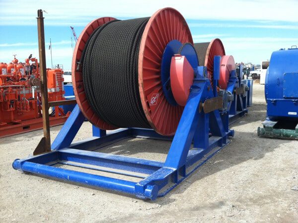
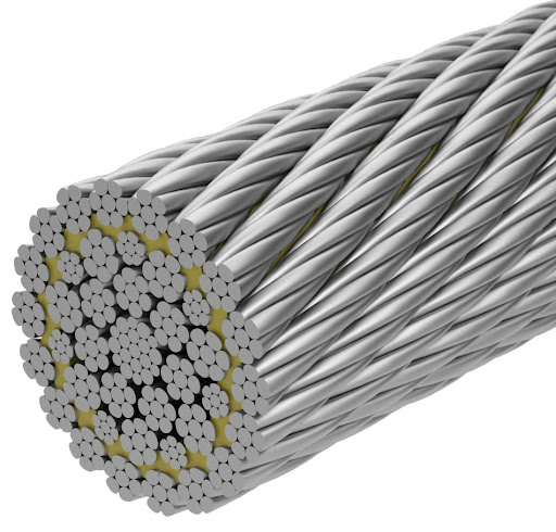
Wire Rope
Drilling steel wire rope is made of steel wire around a central steel wire, and then twists by the rope stand around cable core. Most of drilling line are steel cable core, which is divided into the left-handed and right handed, Material grade is IPS, EIPS, and EEIPS etc. To choose the drilling line according to the hook load, most of model is 6*19S IWRC, diameter is Ø22mm- Ø 30mm, Standard is API 9A and ISO10425.
Except the drilling line, other line we also provide:
9×19S+IWR, 9×19W+IWR, 9×21Fi+ IWR, 9×19S+9×7+Fc. 9×19W+9×7+Fc, 9×21Fi+9×7+Fc,8×19S+Fc, 8×19W+Fc, 8×25Fi+Fc
IWRC 6×Fi(29),IWRC 6×WS(31),IWRC 6×WS(36) 34×7+Fc, 34×7+IWS, 36×7+Fc, 36×7+IWS, 17×7+Fc, 17×7+IWS, 18×7+Fc, 18×7+IWS, 18×19+Fc, 18×19+IWS, 18×19S+Fc, 18×19S+IWS, 18×19W+Fc, 18×19W+IWS Etc.
| Diameter | Approximate Mass Kg/100M | Strength | ||||||||||
| 1570 | 1670 | 1770 | 1870 | 1960 | ||||||||
| Min. breaking force (kN) | ||||||||||||
| FC | IWRC | FC | IWRC | FC | IWRC | FC | IWRC | FC | IWRC | FC | IWRC | |
| 16 | 109 | 118 | 150 | 166 | 159 | 176 | 169 | 187 | 179 | 197 | 187 | 207 |
| 18 | 138 | 150 | 190 | 210 | 202 | 223 | 214 | 236 | 226 | 250 | 237 | 261 |
| 20 | 170 | 185 | 234 | 259 | 249 | 275 | 264 | 292 | 279 | 308 | 292 | 323 |
| 22 | 206 | 224 | 283 | 314 | 301 | 333 | 320 | 353 | 338 | 373 | 354 | 391 |
| 24 | 245 | 266 | 337 | 373 | 359 | 397 | 380 | 420 | 402 | 444 | 421 | 465 |
| 26 | 287 | 312 | 396 | 438 | 421 | 466 | 446 | 493 | 472 | 521 | 494 | 545 |
| 28 | 333 | 366 | 459 | 508 | 488 | 540 | 518 | 572 | 547 | 604 | 573 | 633 |
| 30 | 382 | 416 | 527 | 583 | 561 | 620 | 594 | 657 | 628 | 693 | 658 | 726 |
| 32 | 435 | 473 | 600 | 664 | 638 | 705 | 676 | 747 | 714 | 789 | 749 | 826 |
| 34 | 491 | 534 | 677 | 749 | 720 | 796 | 763 | 843 | 806 | 890 | 845 | 933 |
| 36 | 551 | 598 | 759 | 840 | 807 | 893 | 856 | 945 | 904 | 998 | 947 | 1046 |
| 38 | 614 | 667 | 846 | 936 | 899 | 995 | 953 | 1053 | 1010 | 1112 | 1056 | 1165 |
| 40 | 680 | 739 | 937 | 1037 | 997 | 1102 | 1060 | 1167 | 1120 | 1232 | 1170 | 1291 |
| 42 | 750 | 815 | 1030 | 1143 | 1100 | 1215 | 1160 | 1287 | 1230 | 1359 | 1290 | 1562 |
| 44 | 823 | 894 | 1130 | 1254 | 1210 | 1333 | 1280 | 1412 | 1350 | 1491 | 1415 | 1707 |
| 46 | 899 | 977 | 1240 | 1371 | 1320 | 1457 | 1400 | 1544 | 1480 | 1630 | 1547 | 1859 |


Reviews
There are no reviews yet.